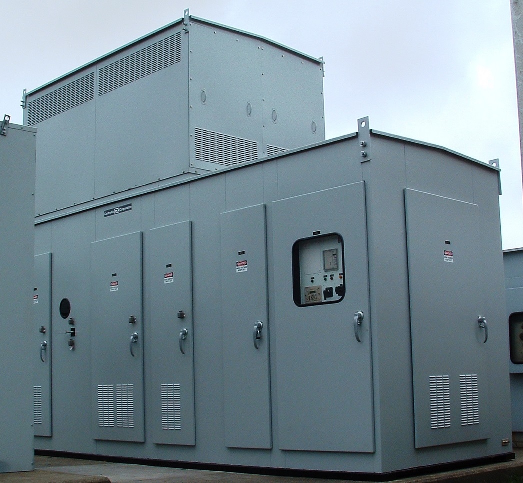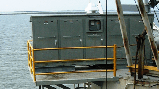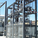
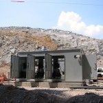
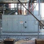
 Summary: Controllix Corporation transitioned a coastal utility from using open rack style capacitor banks to their advanced metal-enclosed capacitor banks. This change notably improve...
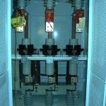
Medium Voltage Capacitor Bank Specifications
Click here to view and download the specs
MEDIUM VOLTAGE MULTISTEP FILTER BANK SPECIFICATION
I. SCOPE
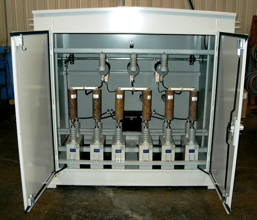
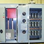
A. This specification covers the electrical characteristics and mechanical features of three phase, 60 Hertz, self-contained, metal enclosed harmonic filter bank. The application of this unit is for power factor improvement without adverse system interactions.
B. This unit shall meet all applicable provisions of ANSI, IEEE, NEMA, and ASTM.
II. GENERAL REQUIREMENT AND RATING
A. Furnish one (1) metal enclosed harmonic filter banks tuned to the 4.2nd harmonic as follows: 9000kVAr effective with one (1) fixed stage of 4000kVAr and two (2) automatically switched stages of 2500kVAr each, 13,800Volts, 95kVbil, 3phase, 60 Hertz, Ungrounded Wye Connected, indoor/outdoor.
B. The equipment shall be factory assembled and tested prior to shipment and, in general, consist of the following:
1. Incoming Section with provisions for the following:
a. Incoming Line Lugs
b. Group-Operated Disconnect Switch
c. Surge Arrestors
d. Potential Transformers
e. Control Power Transformers
f. Current Transformers
2. Capacitor Section with provisions for the following:
a. Vacuum Switches: three (3) single-phase 15kV, 200A vacuum switches per switched stage.
b. Capacitor Fuses: one (1) per capacitor
c. Iron Core Reactors
d. Main Bus
e. Ground Bus
f. Ground Switch
g. Heating and Ventilation Equipment
3. Control Section
a. Controller
b. Relays
c. Lights
III. ENCLOSURE
A. General
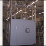
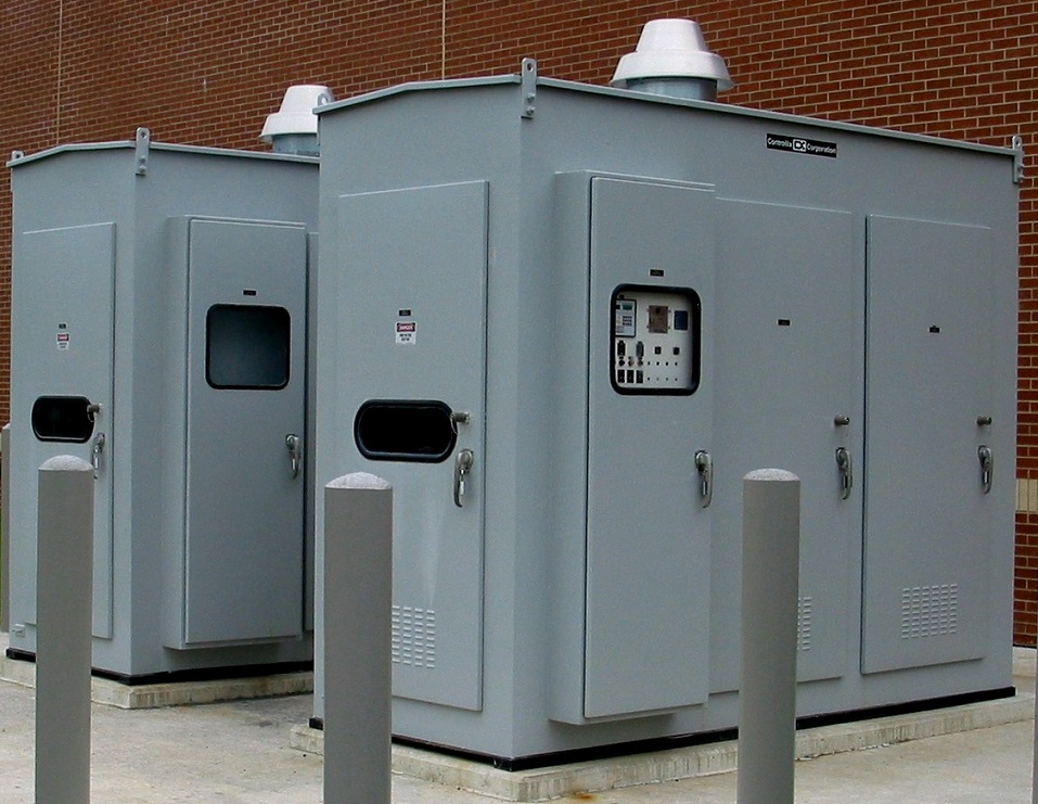
1. Enclosure to be pad mounted self supporting steel structure of a fully welded construction with necessary provisions for ventilation and handling. It shall be fabricated from #11 gauge minimum U.S. Standard sheet metal. The enclosure shall be constructed such that it can be moved by a crane or forklift and lifted, slid or rolled into place on a pad without damage to any portion of the enclosure or its contents.
2. There shall be thermostatically controlled heaters for condensation control located in all non-ventilated compartments.
3. The enclosure shall utilize a highly corrosion-resistant finishing system. All surfaces shall undergo a thorough pre-treatment process before any protective coatings are applied. Protective coatings shall be applied after pre-treatment that resist corrosion and protect the steel enclosure.
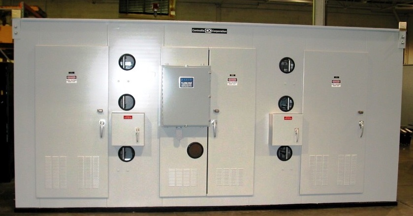
4. The enclosure shall have hinged doors with padlock provisions to provide access to all components of the capacitor bank. The doors shall have 3-point latches. Door stops shall be provided on all doors to limit the door swing to 90° and prevent the doors from being blown shut. Removable bolted panels shall also be provided for maintenance and access to all components.
5. Doors shall feature bulkhead style doors and all-welded construction for long-term durability and weatherproof operation.
6. Viewing windows to permit visual observation of the position of the disconnect switch and ground switch are to be provided.
7. A structural steel base is to be provided. The entire base is to be undercoated with a black, phenolic coating for additional protection against environmental conditions.
8. As evidence of durability, enclosure and construction will be certified by a registered professional engineer to comply with Seismic Zone 4 requirements.
9. The enclosure shall be equipped with vents for ventilation. Vents will be provided with aluminum filters to prevent dust and insect entry. Filters are to be removable for cleaning purposes.
10. The capacitor bank shall be comprised of three sections electrically separated via #12 gauge minimum steel barriers. Each section of the unit shall be an integral part of the enclosure. Bolted construction will not be acceptable. The three sections are the incoming, capacitor and control sections.
11. Thermostatically controlled forced air ventilation shall be provided in the capacitor and reactor sections.
12. Aluminum/copper bus shall be provided and properly sized to handle continuous current rating of capacitor bank. Horizontal main bus shall feed the individual steps from the incoming line section. Provisions shall be made to allow for the expansion of the bank in the future. Bus shall be uninsulated, round edge, electrical-grade copper bar.
13. Barriers between compartments shall extend from floor to ceiling. Bus shall extend through feed-through bushings within barriers.
14. The enclosure shall be equipped with four (4) removable lifting hooks which bolt directly to the top corners of the enclosure.
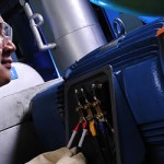
B. Incoming Section
1. Disconnect Switch: This section shall include a 15kV, 600Amp, load break disconnect switch for isolation/servicing of the capacitor bank. Disconnect switch shall utilize direct drive handle. Chain drive will not be acceptable.
2. Control Power Transformer: One (1) 13,800/120 Volt, 3 kVA, oil filled control power transformer shall be provided for 120 Vac control power and voltage for the power factor controller.
C. Capacitor Section
1. Single-Phase Capacitor Units: Capacitors shall be low loss, 2 bushing, single phase,
properly sized and connected per the specification. The capacitors shall have the following
features:
a. Internal discharge resistors to drain voltage to 50 volts or less in five minutes.
b. Suitable for operation at 110 percent of rated voltage, and 135 percent of rated current.
c. Edge stress on the dielectric fluid will be reduced by using rolled edge foil.
d. Shall not contain PCB’s.
e. Capacitors will have passed transient overvoltage endurance testing.
2. Individual Capacitor Current Limiting Fuses: A current limiting capacitor fuse with
current and voltage ratings appropriate for that capacitor shall protect each capacitor.
3. Vacuum Switch: Each switched stage shall be switched via a capacitor rated switching
device with appropriate voltage and current ratings for the system design. The vacuum
switches will have been tested for capacitor switching and meet the following criteria:
Solenoid operated, rated for 50,000 operations (open & close), do not utilize oil or gas
insulation and utilize porcelain housing.
4. Ground Switch: One three pole, group operated ground switch shall be provided to
ground and short the main phase bus of the capacitor bank. Upon locking the ground
switch in the closed position, the individual step vacuum switching devices shall
sequentially and temporarily close into the main phase bus and ground the capacitors.
Ground switch must be direct-drive. Chain driven drive not acceptable.
5. Iron-Core Reactors: The harmonic filter bank shall be equipped with single-phase ironcore
reactors. Reactors shall be equipped with copper or aluminum windings and a 220
Degree C. insulation system with a 115 Degree C temperature rise over a 40 Degree C.
ambient.
a. Reactors shall be rated as follows:
9000 kVAr Banks:
Tuning kVAr I RMS I 1 I 5 I 7 I 11 I 13 I 17 I 19
Stage
1 4.2 4000 212.61 192.45 83.67 33.47 3.35 3.35 3.35 3.35
Stage
2 4.2 2500 132.88 120.28 52.30 20.92 2.09 2.09 2.09 2.09
Stage
3 4.2 2500 132.88 120.28 52.30 20.92 2.09 2.09 2.09 2.09
b. Reactors shall be tested according to the exact amounts of fundamental and harmonic
frequency currents as specified. A report of such testing shall be provided.
Mathematical modeling shall not be acceptable.
c. To reduce gap magnetic losses and extraneous magnetic fields, reactor design shall
utilize at least twelve (12) individual gaps per phase.
d. Reactors shall have taps at +/- 5%.
D. Control Section
1. VAR Sensing Controller: This section shall include a power factor controller with a digital power factor meter.
a. The controller shall provide complete, automatic control and allow for manual switching control for the bank in order to maintain optimum power factor regulation.
b. The controller shall provide indication of Total Harmonic Distortion on Voltage (THD V%) and Total Harmonic Distortion on Current (THD I%).
c. Controller shall feature a large graphics display (at least 64 x 132 pixels) and monitor the following: Active Power (kW), Apparent Power (kVA), reactive power (kVAr), reactive power to reach the target power factor, Voltage, Current, Total Harmonic Distortion on Voltage (THD V %) and Total Harmonic Distortion on Current (THD I%).
2. PLC: A programmable logic controller shall be provided. This controller will provide relaying and timing functions otherwise needed by individual components.
3. Manual Control Switches: On-Off-Auto toggle switches shall be provided for operation of the switched steps.
4. Circuit breakers shall be provided for operation of the heater and ventilator circuit.
5. Lights: Capacitor “Step on” indicating lights shall be provided.
6. Operations Counter: Each switched stage shall have an operations counter to log close
operations for maintenance and statistical purposes.
7. Output Contacts for each stage consisting of a pair of electrically separate “A” and “B”
contacts maintained to allow for operation of switching devices.
8. Key Release: Solenoid key release unit shall be located in this compartment (see key
interlock system below).
IV. KEY INTERLOCK SYSTEM
A. A solenoid key interlock shall be provided such that the key to operate the disconnect switch
cannot be removed unless all the capacitor switching devices have been open for five minutes.
Removal of the key will disable the “normal” control of the capacitor switching devices.
B. The disconnect switch cannot open unless the solenoid key is available. The disconnect shall
not closed unless the ground switch is locked open.
C. The ground switch cannot close unless the disconnect switch is locked open. The ground
switch cannot open unless all the capacitor section doors have been locked closed.
D. The capacitor compartment doors shall not open unless the ground switch is locked closed.
V. BANK PROTECTION
Provisions shall be included to alarm the customer in the event power factor or harmonics are not
within stated guidelines.
VI. TESTING
All testing shall be performed in accordance with NETA Sections 7.20.1 and 70.20.2 under actual
standards and conditions. Certified test reports shall be provided.
VII. MISCELLANEOUS
A. One remote current transformer (5VA minimum) for the VAr controller to be provided by
customer for each bank.
B. Equipment shall be neatly constructed and finished.
C. Bank shall be supplied with appropriate cautionary nameplates.
D. Any miscellaneous components not specifically named, but required for proper operation, shall
be included.
E. Filter bank manufacturer to have over 20 years of experience as a supplier to major utilities
and industrial partners. References to be provided with proposal.
VIII. Approvals
The following information shall be submitted for approval for overall bank coordination:
A. Outline drawings complete with elevations, sections, base plan, anchoring information and
weight.
B. Bill of Material.
C. Control Schematic
D. Three-Line Diagram.