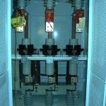
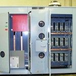
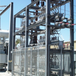
 Summary: Controllix Corporation transitioned a coastal utility from using open rack style capacitor banks to their advanced metal-enclosed capacitor banks. This change notably improve...
Harmonics (electrical power)
Harmonic is multiple of the fundamental frequency and it can be voltage and current in an electric power system are a result of non-linear electric loads. Harmonic frequencies in the power grid are a frequent cause of power quality problems. Harmonics in power systems result in increased heating in the equipment and conductors, misfiring in variable speed drives, and torque pulsations in motors. Reduction of harmonics is considered desirable.
Current harmonics
In a normal alternating current power system, the current varies sinusoidally at a specific frequency, usually 50 or 60 hertz. When a linear electrical load is connected to the system, it draws a sinusoidal current at the same frequency as the voltage (though usually not in phase with the voltage).
Current harmonics are caused by non-linear loads. When a non-linear load, such as a rectifier is connected to the system, it draws a current that is not necessarily sinusoidal. The current waveform can become quite complex, depending on the type of load and its interaction with other components of the system. Regardless of how complex the current waveform becomes, as described through Fourier series analysis, it is possible to deconstruct it into a series of simple sinusoids, which start at the power system fundamental frequency and occur at integer multiples of the fundamental frequency.
Further examples of non-linear loads include common office equipment such as computers and printers, Fluorescent lighting, battery chargers and also variable-speed drives.
In power systems, harmonics are defined as positive integer multiples of the fundamental frequency. Thus, the third order harmonic is the third multiple of the fundamental frequency. This type of harmonics is generated in non-linear loads. Examples of nonlinear loads include transistors, electrical motors, and the non-ideal transformer. Non-linear loads create disturbances in the fundamental harmonic, which produce all types of harmonics. However, in this section we focus on the 3rd order harmonic due to its certain special characteristics in the context of powers systems.[1]
Power is supplied by a three phase system, where each phase is 120 degrees apart. This is done for two reasons: Firstly it is because generators/motors that use three phases are more efficient due to the constant torque the phases supply, and secondly it is because after power is supplied to a load, the three phases can theoretically be added onto a neutral wire and cancel each other out. This saves the utility from creating return wiring to the power plant. However, if the 3 phases contain 3rd order harmonics, the currents will not fully add to zero. As seen in the figure, the 3rd harmonic will add constructively with the 3rd harmonics within the other phases. This leads to an oscillating current in the neutral wire, which can be dangerous since it is designed (i.e. small-size conductors) to carry minimal current.[1] To avoid 3rd harmonics adding together Delta connections are used, and the current is cycled around the connection instead of combining into the neutral of a Wye connection.
Voltage harmonics
Voltage harmonics are mostly caused by current harmonics. The voltage provided by the voltage source will be distorted by current harmonics due to source impedance. If the source impedance of the voltage source is small, current harmonics will cause only small voltage harmonics. It is typically the case that voltage harmonics are indeed small compared to current harmonics. For that reason, the voltage waveform can usually be approximated by the fundamental frequency of voltage. If this approximation is used, current harmonics produce no effect on the real power transferred to the load. An intuitive way to see this comes from sketching the voltage wave at fundamental frequency and overlaying a current harmonic with no phase shift (in order to more easily observe the following phenomenon). What can be observed is that for every period of voltage, there is equal area above the horizontal axis and below the current harmonic wave as there is below the axis and above the current harmonic wave. This means that the average real power contributed by current harmonics is equal to zero. However, if higher harmonics of voltage are considered, then current harmonics do make a contribution to the real power transferred to the load.
Harmonics fundamentals
Harmonics provides a mathematical analysis of distortions to a current or voltage waveform. Based on Fourier series, harmonics can describe any periodic wave as a summation of simple sinusoidal waves which are integer multiples of the fundamental frequency.
Harmonics are steady-state distortions to current and voltage waves and repeat every cycle. They are different from transient distortions to power systems such as spikes, dips and impulses.[2]
Total harmonic distortion
Total harmonic distortion, or THD is a common measurement of the level of harmonic distortion present in power systems. THD can be related to either current harmonics or voltage harmonics, and it is defined as the ratio of total harmonics to the value at fundamental frequency times 100%.
- {\displaystyle \mathrm {THD_{V}} ={\frac {\sqrt {V_{2}^{2}+V_{3}^{2}+V_{4}^{2}+\cdots +V_{n}^{2}}}{V_{1}}}*100\%={\frac {\sqrt {\sum _{k\mathop {=} 2}^{n}V_{k}^{2}}}{V_{1}}}*100\%}
- {\displaystyle {THD_{I}}={\frac {\sqrt {I_{2}^{2}+I_{3}^{2}+I_{4}^{2}+\cdots +I_{n}^{2}}}{I_{1}}}*100\%={\frac {\sqrt {\sum _{k\mathop {=} 2}^{n}I_{k}^{2}}}{I_{1}}}*100\%}
where Vn is the RMS voltage of nth harmonic, In is the RMS current of the nth harmonic, and n = 1 is the fundamental frequency.
It is usually the case that we neglect higher voltage harmonics; however, if we do not neglect them, real power transferred to the load is affected by harmonics. Average real power can be found by adding the product of voltage and current (and power factor, denoted by pf here) at each higher frequency to the product of voltage and current at the fundamental frequency, or
- {\displaystyle {P_{avg}}=\sum _{k\mathop {=} 1}^{\infty }V_{k}*I_{k}*pf=P_{avg,1}+P_{avg,2}+\cdots }
where Vk and Ik are the RMS voltage and current magnitudes at harmonic k ({\displaystyle k=1} denotes the fundamental frequency), and {\displaystyle P_{avg,1}} is the conventional definition of power without factoring in harmonic components.
It must be noted that the power factor mentioned above is the displacement power factor. There is another power factor that depends on THD. True power factor can be taken to mean the ratio between average real power and the magnitude of RMS voltage and current, {\displaystyle pf_{true}={\frac {P_{avg}}{V_{rms}I_{rms}}}}.[3]
- {\displaystyle {V_{rms}}=V_{1,rms}{\sqrt {1+\left({\frac {THD_{V}}{100}}\right)^{2}}}}
and
- {\displaystyle {I_{rms}}=I_{1,rms}{\sqrt {1+\left({\frac {THD_{I}}{100}}\right)^{2}}}}
Substituting this in for the equation for true power factor, it becomes clear that the quantity can be taken to have two components, one of which is the traditional power factor (neglecting the influence of harmonics) and one of which is the harmonics’ contribution to power factor:
- {\displaystyle {pf_{true}}={\frac {P_{avg}}{V_{1,rms}I_{1,rms}}}*{\frac {1}{{\sqrt {1+\left({\frac {THD_{V}}{100}}\right)^{2}}}{\sqrt {1+\left({\frac {THD_{I}}{100}}\right)^{2}}}}}.}
Names are assigned to the two distinct factors as follows:
- {\displaystyle pf_{true}=pf_{disp}*pf_{dist},}
where {\displaystyle pf_{disp}} is the displacement power factor and {\displaystyle pf_{dist}} is the distortion power factor (i.e. the harmonics’ contribution to total power factor).
Effects
One of the major effects of power system harmonics is to increase the current in the system. This is particularly the case for the third harmonic, which causes a sharp increase in the zero sequence current, and therefore increases the current in the neutral conductor. This effect can require special consideration in the design of an electric system to serve non-linear loads.[4]
In addition to the increased line current, different pieces of electrical equipment can suffer effects from harmonics on the power system.
Motors
Electric motors experience losses due to hysteresis and eddy currents set up in the iron core of the motor. These are proportional to the frequency of the current. Since the harmonics are at higher frequencies, they produce higher core losses in a motor than the power frequency would. This results in increased heating of the motor core, which (if excessive) can shorten the life of the motor. The 5th harmonic causes a CEMF (counter electromotive force) in large motors which acts in the opposite direction of rotation. The CEMF is not large enough to counteract the rotation, however it does play a small role in the resulting rotating speed of the motor.
Telephones
In the United States, common telephone lines are designed to transmit frequencies between 300 and 3400 Hz. Since electric power in the United States is distributed at 60 Hz, it normally does not interfere with telephone communications because its frequency is too low.
Sources
A pure sinusoidal voltage is a conceptual quantity produced by an ideal AC generator built with finely distributed stator and field windings that operate in a uniform magnetic field. Since neither the winding distribution nor the magnetic field are uniform in a working AC machine, voltage waveform distortions are created, and the voltage-time relationship deviates from the pure sine function. The distortion at the point of generation is very small (about 1% to 2%), but nonetheless it exists. Because this is a deviation from a pure sine wave, the deviation is in the form of a periodic function, and by definition, the voltage distortion contains harmonics.
When a sinusoidal voltage is applied to a linear load, such as a heating element, the current through it is also sinusoidal. In non-linear loads, the current varies non-proportionally to the voltage, so the current through them has a nonsinusoidal waveform.
When there is significant impedance in the path from the power source to a nonlinear load, these current distortions will also produce distortions in the voltage waveform at the load. However, in most cases where the power delivery system is functioning correctly under normal conditions, the voltage distortions will be quite small and can usually be ignored.
Waveform distortion can be mathematically analysed to show that it is equivalent to superimposing additional frequency components onto a pure sinewave. These frequencies are harmonics (integer multiples) of the fundamental frequency, and can sometimes propagate outwards from nonlinear loads, causing problems elsewhere on the power system.
The classic example of a non-linear load is a rectifier with a capacitor input filter, where the rectifier diode only allows current to pass to the load during the time that the applied voltage exceeds the voltage stored in the capacitor, which might be a relatively small portion of the incoming voltage cycle.
Other examples of nonlinear loads are battery chargers, electronic ballasts, variable frequency drives, and switching mode power supplies.


