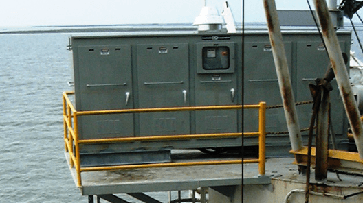
 Summary: Controllix Corporation transitioned a coastal utility from using open rack style capacitor banks to their advanced metal-enclosed capacitor banks. This change notably improve...
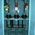
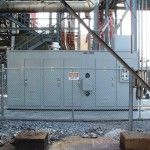
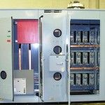
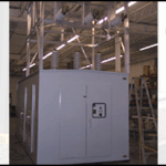
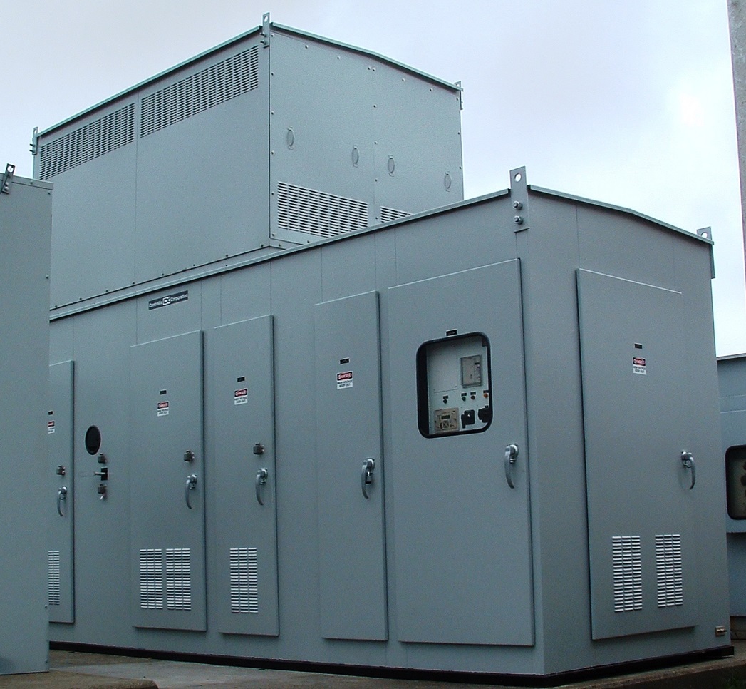
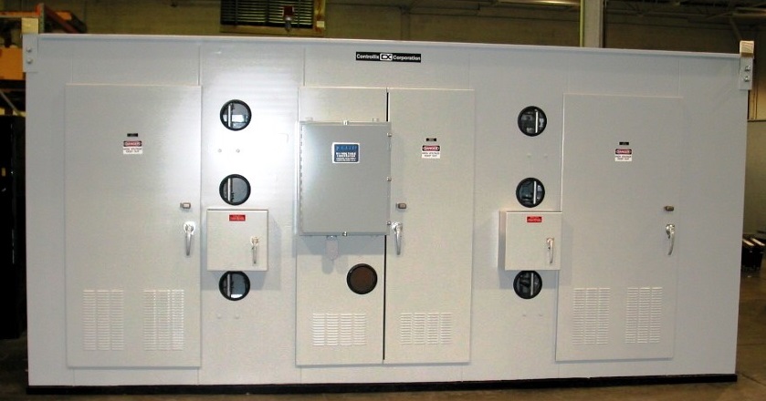
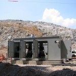
Pad Mount Capacitor Banks
Click here to view and download the specs
MEDIUM VOLTAGE PAD MOUNT CAPACITOR BANK SPECIFICATION
I. SCOPE
A. This specification covers the electrical characteristics and mechanical features of a three
phase, 50 or 60 Hertz, self-contained, pad mounted, metal enclosed capacitor bank.
B. This unit shall meet all applicable provisions of ANSI, IEEE, NEMA, AND ASTM.
II. GENERAL REQUIREMENT AND RATING
Furnish one metal enclosed capacitor bank as follows:
_____kVAr nominal with automatically and manually switched step of _____kVAr each,
_____Volts, _____kVbil, 3 phase, 50/60 Hertz, ________Connected, indoor/outdoor,
_____/_____Amps available short circuit current (asymmetrical/symmetrical).
III. STANDARDS
A. The equipment shall be CSA approved.
B. The manufacturer of the equipment shall possess blanket certification of the equipment for
Seismic Zone 4.
IV. ENCLOSURE
A. General
1. Enclosure to be pad-mounted self-supporting steel structure fabricated from #12 gauge
minimum U.S. Standard sheet metal.
2. The enclosure shall have hinged doors with padlock provisions to provide access to all
components of the capacitor bank. The doors shall have 3-point latches.
3. A structural steel base is to be provided. The entire base is to be undercoated for
additional protection against environmental conditions. The enclosure shall have an
open bottom with a “C” channel with a 2” lip for strength and ease of mounting to the
pad.
4. Aluminum screens are to be provided to prevent dust and insect entry. Screens are to be
removable for cleaning purposes.
5. The capacitor bank shall be comprised of a single compartmentalized enclosure that
houses all components, including fuses, capacitors, switches and control. The front of
the enclosure shall have a dead-front compartment and a control compartment. The rear
of the enclosure shall be of live-front design.
6. Aluminum/copper bus shall be provided and properly sized to handle continuous current
rating of capacitor bank.
7. The enclosure roof shall be cross-kinked for water run-off and rigidity.
8. The enclosure shall utilize a highly corrosion-resistant finishing system. All surfaces shall
undergo a thorough pretreatment process before any protective coatings are applied.
Protective coatings shall be applied, after pretreatment that resist corrosion and protect
the steel enclosure. All sheet metal external welds and seams must be ground and
sanded smooth. All sheet metal internal welds and seams must be wire brushed. All
structural base and frame welds to have slag and all spatter removed. All surfaces shall
be cleaned for painting with the acid pickle treatment or equal. All surfaces shall be free
of dirt, oil, grease, rust, scale and weld spatter. Primer shall be applied at a minimum
depth of .001″ to all steel surfaces. Primer shall be completely dry and free of runs
before finish coat is applied. Finish coats (2) shall be a minimum of .002″ thick or more
as necessary for complete coverage. No primer shall be visible through the finish coat.
Finish will be free of runs and scratches. After assembly and preparation for shipment,
unit will be inspected for scratches, scuffs or blemishes and re-touch as required.
B. Equipment Front Section (Incoming Dead-Front Compartment and Control)
1. Contains bushing wells that accept load-break bushing well inserts.
2. Contains parking stands, ground bus and a hinged Lexan viewing window. The hinged
Lexan window allows for visible inspection of the blown fuse indicators, as well as
providing access to the blown fuses.
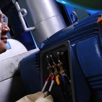
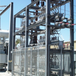
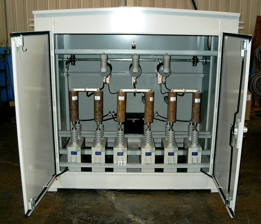
C. Equipment Rear Section (Live-Front Compartment)
1. Capacitors shall be non-PCB, low loss, 2 bushing, single phase, properly sized and
connected per the specification. The capacitors shall have the following features:
a. Internal discharge resistors to drain voltage to 50 volts or less in five minutes.
b. Suitable for operation at 110 percent of rated voltage, and 135 percent of rated
current.
2. A current limiting capacitor fuse with current and voltage ratings appropriate for the
capacitor shall protect each capacitor.
3. Capacitors shall be switched via a vacuum switching device with appropriate voltage and
current ratings for the system design. Switches shall be mounted to allow manual
operation, visual positioning and easy removal if necessary.
4. _____ class arresters shall be provided for lightning protection.
5. One oil-filled control power transformer shall be provided for 120 Vac control power and
voltage for the power factor controller. Alternatively, power can be supplied by the user.
D. Control Section
1. A four or six terminal socket shall be mounted in the control section, isolated from the
bushings by a metal barrier, that accepts standard utility grade capacitor controls.
V. QUALITY CONTROL SYSTEM
A. Supplier shall provide with its bid a quality manual that describes in detail company policy
with regard to a quality system such as ISO 9000 or equivalent. The quality manual shall
provide information regarding the following:
a) Distribution and Manual Control
b) Quality Policy
c) Organization Chart
d) Management Responsibility
e) Quality System
f) Contract Review
g) Design Control
h) Document Control
i) Purchasing
j) Purchaser Supplied Products
k) Product Identification and Traceability
l) Process Control
m) Inspection and Testing
n) Inspection, Measuring, and Test Equipment
o) Inspection and Test Status
p) Control of Non-Conforming Product
q) Corrective and Preventive Action
r) Handling, Storage, Packaging, Preservation & Delivery
s) Quality Records
t) Internal Quality Audits
u) Training
v) Servicing
w) Statistical Techniques
B. Supplier will have a documented history of manufacturing pad-mounted capacitor banks at
the given location for over five (5) years.
VI. OTHER
A. Interconnection wiring to be done by others.
B. Acceptable manufacturers of the capacitor bank are as follows:
Controllix Corporation
21415 Alexander Road
Walton Hills, OH 44146