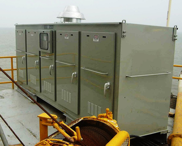
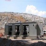
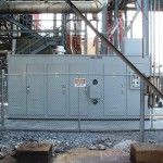
 Summary: Controllix Corporation transitioned a coastal utility from using open rack style capacitor banks to their advanced metal-enclosed capacitor banks. This change notably improve...
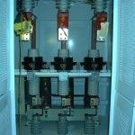
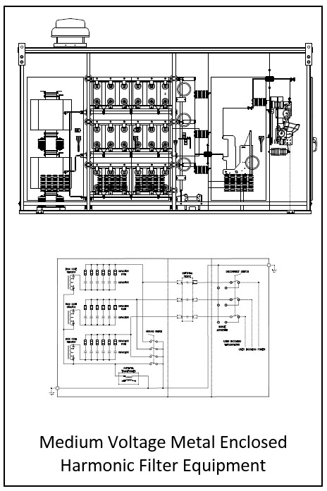
Medium Voltage Harmonic Filter Banks
Controllix Corporation Medium Voltage Harmonic Filter Banks reduces harmonic distortion, improves power factor, and increases system performance resulting in significant cost savings. Consisting of capacitors, reactors and resistors, harmonic filter banks provide a low impedance route out of the system for harmonics. The series capacitor/reactor combination prevents resonance by tuning the network below the first dominant harmonic (usually the 5th or 300Hz). Since three phase networks typically have little or no harmonic current below the fifth, there is no energy available to resonate. Distortion is reduced to required levels. The metal-enclosed design provides maximum environmental protection and safety, while maintaining a compact installation footprint.
Controllix Filter Banks accommodate 2.4kV to 34.5kV requirements and are available in single-tuned, multi-tuned and high-pass filter banks. Single-stage or multi-stage configurations can be obtained with iron core or air core reactors.
Controllix has fabricated hundreds of custom-designed passive shunt harmonic filter packages in its 40-year history. Filter banks can be built to a customer’s specifications or designed by our Controllix Engineering Department. We stand ready to perform harmonic studies and collect necessary data. With accurate modeling techniques, the optimum solution can be quickly and reliably identified. Controllix designs and manufactures turnkey systems, installation, and startup.
Controllix Harmonic Filter Banks are typically used when reactive power is required, but the installation of conventional capacitor banks would risk amplifying existing distortion to excessive levels. We understand the critical role harmonic mitigation and power factor correction play in optimizing the efficiency of power distribution systems. Installation of Controllix filter banks will protect a plant’s distribution system and equipment. Reduced harmonic distortion improves a plant’s productivity by preventing the following problems:
- Motor inefficiency
- Blown capacitor fuses
- False operation of breakers and fuses
- Abnormal heating of equipment (e.g., transformers, switchgear)
- Excessive copper losses within transformers
- Worn conductor insulation
- Measurement errors by utility meters
- Neutral bus bar and lugs overloading
- Phone line interference
- Noise
- Problematic operation of drives and power supplies
Ratings:
Standard voltage ratings are 2.4kV through 34.5kV. Units comply with NEC, IEEE and ANSI standards.
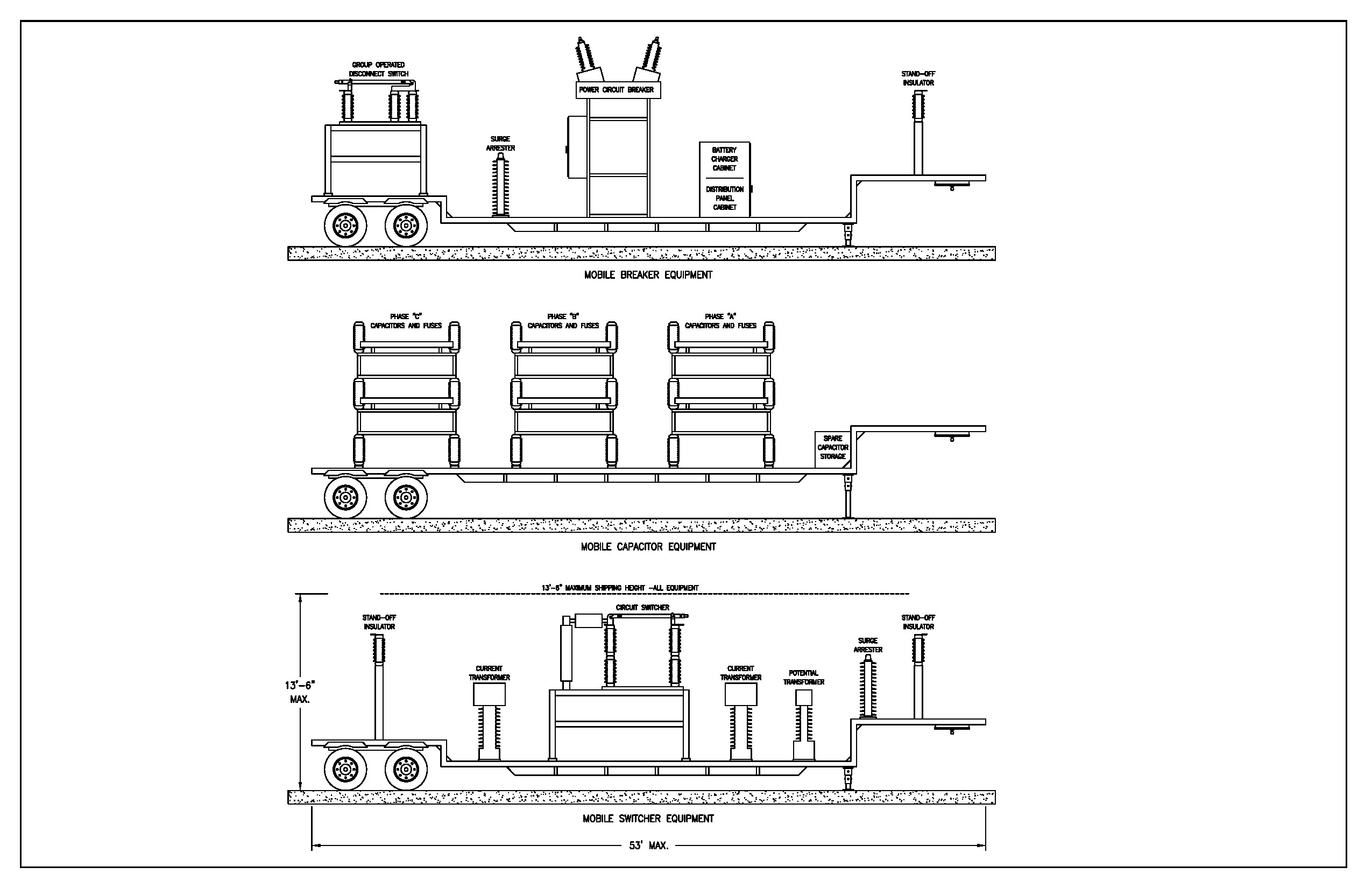
Diagram:
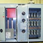
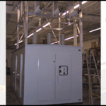
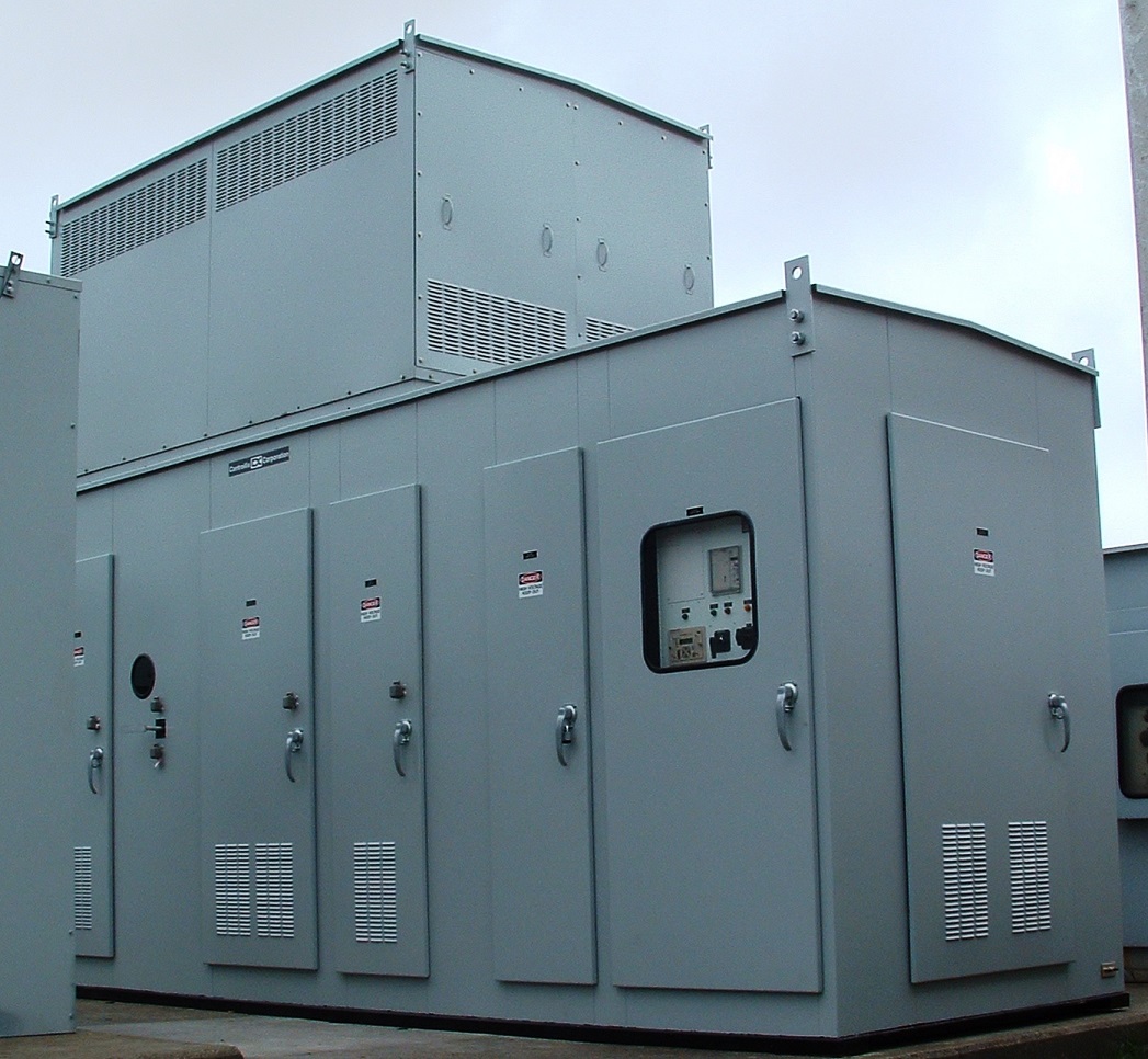
Construction:
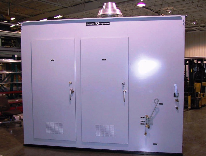
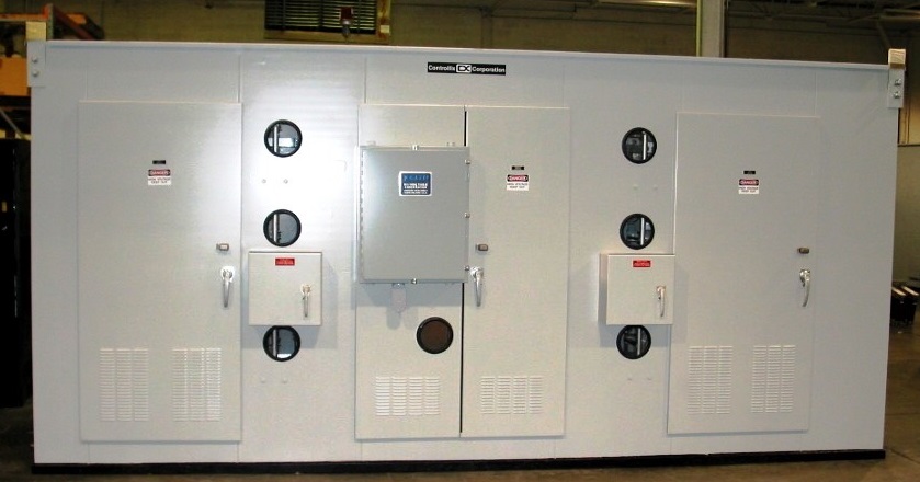
Enclosures feature fully welded construction of sturdy 11-gauge carbon steel with a structural steel base. Doors are internally hinged and have 3-point latching with provisions for padlocking. The enclosure is processed to inhibit rust with a phosphate base preparation, followed with primer and the standard ANSI #61 gray enamel finish. The base of the enclosure is undercoated. Other colors are available upon request. Ventilation and heaters are provided to meet requirements.
Harmonic Filter Reactors:
Reactors are air core, iron core or oil-filled types and are sized for tuning (or detuning) a specific harmonic order and percentage of the harmonic order current. Reactor placement may be part of the capacitor section(s) and may require its own reactor section(s), or may be stand-alone.
Disconnect Switch:
The incoming compartment typically contains an externally operated, non-load break, three-pole disconnect switch. This device is used as a means to disconnect the capacitor unit from the power system and provide the “visible break” required by the National Electrical Code (NEC).
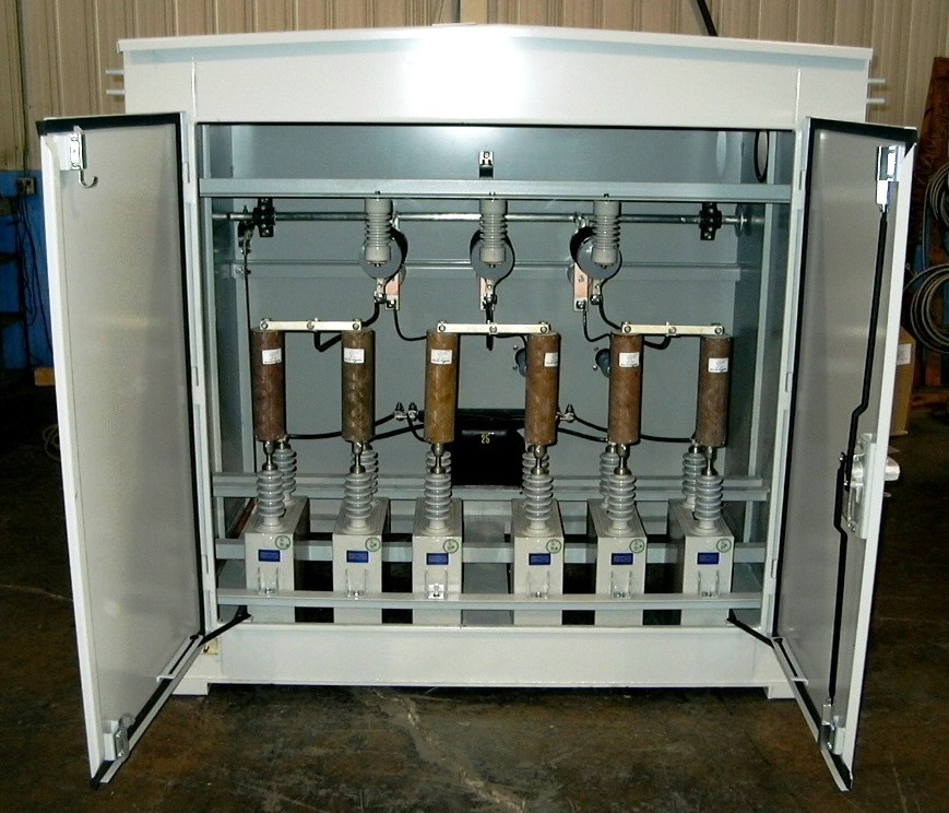
Capacitors:
Single-phase or three-phase capacitors with one, two or three bushings are used. Capacitors comply with IEC, IEEE and CSA standards. Each capacitor is easily removed for ease of inspection and maintenance. Capacitors are equipped with discharge resistors to drain residual voltage within five minutes of de-energizing. The dielectric is biodegradable, environmentally friendly and non-toxic. The capacitors are rated at 115% of the system’s nominal voltage rating to account for the fundamental voltage rise and harmonic voltages.
Capacitor Fuses:
Each capacitor is provided with a properly coordinated current limiting fuse equipped with blown fuse indication.
Controls:
A variety of control technologies are available, including automatic controllers that can bring on stages based on power factor, current, VAr loading or time-of-day. Blown fuse alarms, neutral unbalance protection and networking are also available.
Switching Devices:
For switched applications, stages are controlled by dependable vacuum switches or vacuum contactors.
Harmonic Filter Reactors:
Ground Switch: A manually operated, interlocked ground switch assures additional personnel safety by discharging stored energy from the capacitors and/or disconnect switch. The ground switch is designed for quick, easy operation.
Interlock System:
Units are provided with a key interlock system preventing entrance into the unit while the unit is energized.
Harmonic Filter Reactors:
Bus Systems: Copper and aluminum main and ground bus are used, along with polymer or porcelain support insulators.
Unbalance Detection Scheme: Harmonic filter banks are connected in either delta or ungrounded wye to prevent harmonics from contributing to system ground problems.
PT (Neutral to Ground) for Ungrounded Wye Banks
CT (Between Neutrals) for Split Wye Banks
CT on phases for Delta Connections
Options:
Top or Bottom Entry
Control Power Transformer
Remote Alarm Relay
Main Incoming Fuses
Lightning Arresters
Roof Bushings
Zero Voltage Closing Vacuum Switches
Metering or Circuit Monitoring
Current Transformer: A separately mounted CT is required and is available as an option.