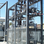
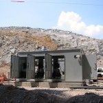
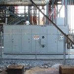
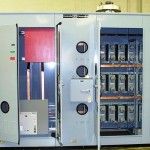
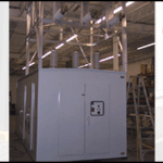
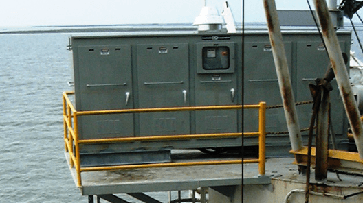
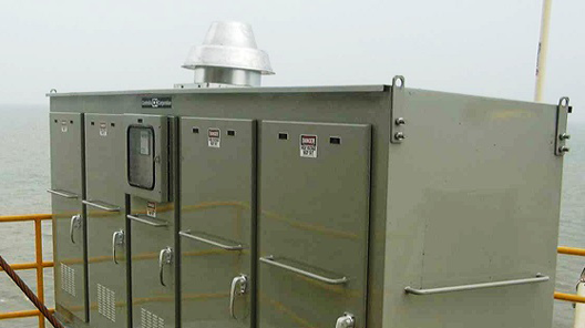
 Summary: Controllix Corporation transitioned a coastal utility from using open rack style capacitor banks to their advanced metal-enclosed capacitor banks. This change notably improve...

Low Voltage Capacitor Bank Specifications
Click here to view and download the specs
LOW VOLTAGE AUTOMATICALLY SWITCHED
CAPACITOR BANK SPECIFICATION
1.0 SCOPE
1.1 This specification describes the necessary requirements for the design, fabrication, and operation of automatically switched, low voltage (600 Volt and below), capacitor banks.
1.2 The equipment described in these specifications shall be furnished by the manufacturer and installed by others in accordance with the manufacturer’s recommendations.
2.0 GENERAL CONSTRUCTION FEATURES
2.1 The capacitor cells, contactors, controller, and related equipment shall be mounted in the same enclosure to minimize field installation.
2.2 Current transformers and associated wiring necessary for VAR sensing are to be supplied and installed by others.
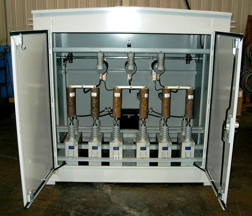
2.3 The capacitor cells, fuses and switching contactor in each step of the capacitor assembly shall be mounted on a removable tray for ease of removal and replacement.
2.4 The standard enclosure shall be rated NEMA 1. This enclosure is intended for indoor use primarily to provide a degree of protection against contact with the enclosed equipment in locations where unusual service conditions do not exist. The following options shall be available:
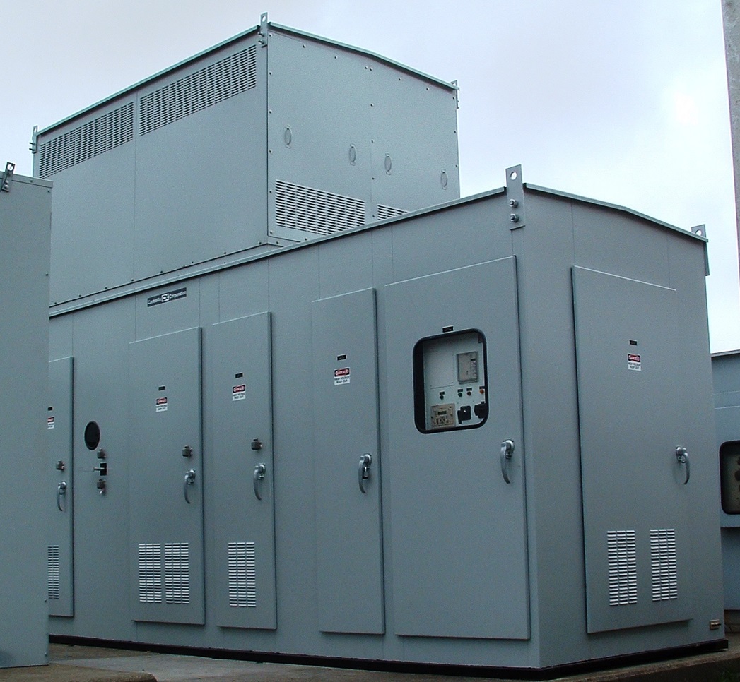
2.4.1 Optional NEMA 3R enclosure with a gasketed control door. This enclosure is intended for outdoor use primarily to provide a degree of protection against falling rain; and to be undamaged by the formation of ice on the enclosure.
2.4.2 Optional NEMA 12 enclosure to include a thermostatically controlled, 10 inch, forced air, direct drive roof ventilator capable of moving 470 cubic foot per minute of free air at 1500 RPM. Air filter elements shall be provided on all external louvers used for cooling air intake.
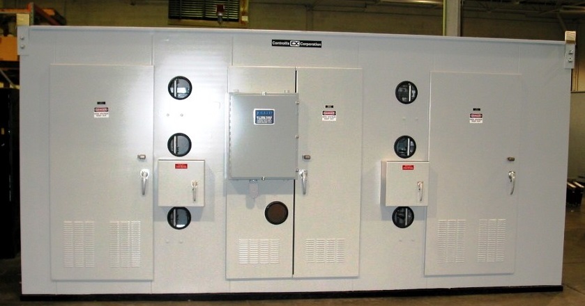
2.4.3 Optional door mounted, blown fuse indicating lights, 1 per phase per step.
2.4.4 Optional breaker with a door interlock. See section 9.2 for breaker specifics.
2.5 Provision shall be made for top or bottom conduit entry into the incoming cable compartment of the enclosure.
2.6 A door mounted, solid state, multi step, adjustable power factor controller shall be provided as part of this equipment. This controller shall automatically switch the steps in and out to provide power factor
correction to a desired set point.
2.7 Current limiting fuses shall be provided on all three phases of each step.
2.8 A voltage transformer of suitable rating shall be provided for control power and voltage sensing. Protection shall be provided with two primary current limiting fuses.
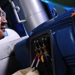
2.9 All internal buswork shall be bare tin plated copper, or insulated copper conductor. All buswork shall be braced for 65,000 Amperes momentary current.
2.10 All flexible power cable shall be copper conductor, 1050C insulation, installed in accordance with the latest revision of the National Electrical Code.
3.0 CAPACITOR CELLS
3.1 The capacitor elements shall be Underwriters Laboratories (UL) listed.
3.2 Each capacitor cell shall be equipped with a Pressure Sensitive Interrupter. The PSI protects the cell from rupture by interrupting capacitor current when the internal pressure forces the cover up, breaking an under cover contact. This provides visual indication of end of life.
3.3 A discharge resistor shall be provided on each capacitor cell to discharge the residual voltage to 50 volts or less within one minute after deenergization.
3.4 The capacitor cells shall be impregnated with a biodegradable, environmentally friendly and non-toxic dielectric fluid.
3.5 The capacitor cells shall be suitable for continuous operation over a temperature range of -400C to +700C.
3.6 The capacitor cells shall be of “low loss” design with losses not to exceed 0.5 watts per KVAR.
3.7 The capacitor cells shall be designed to withstand the duties described in ANSI/IEEE Standard 18 and NEMA CP-1.
4.0 CURRENT LIMITING INDUCTORS
4.1 A three phase, air core inductor shall be connected in series with each of the capacitor steps to minimize inrush current during switching of steps.
4.2 The inrush limiting inductors shall be wound with 900C insulated, copper conductor cable.
5.0 SHORT CIRCUIT PROTECTION
5.1 A 600 V, current limiting fuse shall be provided in each phase of each step of the capacitor assembly. These fuses shall provide the necessary protection against short circuit currents.
5.2 The interrupting rating of the current limiting fuse shall be 200,000 Amperes.
5.3 The fuses for each step shall be mounted in a fuse block located on the same tray as the capacitor cells.
6.0 CONTACTORS
6.1 The individual capacitor steps shall be switched using a contactor suitable for switching capacitive currents.
6.2 The contactor shall use a control voltage of 120 VAC.
6.3 The minimum life expectancy of the contactor shall be one million switching operations.
6.4 The switching operation of the contactor shall be controlled by the power factor controller described in Section 8.0 below.
7.0 CONTROLLER
7.1 A door-mounted controller shall be provided that complies with the following:
7.1.1 Microprocessor based adjustable control.
7.1.2 Manual or Automatic selector switch.
7.1.3 Adjustable target power factor setting from 0.8 inductive (lagging) to 0.95 capacitive (leading)
7.1.4 Adjustable switching time delay from 10 to 60 seconds.
7.1.5 Fault signaling output relay if target power factor is not reached.
7.1.6 Continuous front panel display indicating which steps are on.
7.1.7 Digital display of actual power factor.
7.1.8 No volt release of all output contacts when the supply voltage has been interrupted for 35 ms. This serves to protect the capacitors after the power has been restored.
7.1.9 Rotational switching program to assure that the steps are used equally. The first step turned on is the first step turned off.
7.1.10 Operating range from 14°F (-10°C) to 131°F (55°C). As an adder, the operating range shall be extendable to -31°F (-350C) to 158°F (70°C).
8.0 INCOMING POWER CONNECTION
8.1 If a main circuit breaker is not specified, the incoming power connection shall be to a 1200 Ampere lug capable of accommodating the following incoming cables:
Four 250-500 kcmil Aluminum conductors
Four 250-350 kcmil Copper conductors
– suitable for 500 kcmil copper, 1200 amp rating
8.2 If a main circuit breaker is specified, it shall comply with the following:
8.2.1 GE Spectra RMS current limiting design.
8.2.2 600 Volt, 65KA interrupting capacity.
8.2.3 Solid state trip mechanism, with interchangeable rating plugs.
8.2.4 Safety door interlock to trip breaker if enclosure door is opened
while unit is energized.
8.2.5 The incoming power cable connections shall be appropriately
sized for the breaker.
9.0 ENCLOSURE
9.1 The capacitor enclosure shall be of NEMA 1 construction.
9.2 The structure of the capacitor enclosure shall be constructed of 11 gauge steel.
9.3 The capacitor enclosure shall be painted with ANSI 61 gray, acrylic urethane paint.
9.4 The enclosure shall be equipped with louvered side panels to provide cooling air intake.
9.5 The enclosure shall be front access with removable side and back panels.
9.6 The enclosure door handle shall be provided with a key lock.
9.7 The enclosure shall be provided with four, top mounted lifting eyes.
10.0 WARRANTY/DISCLAIMERS
10.1 The switched capacitor assembly shall be warranted by the manufacturer to be free from defects for a period of 18 months from factory shipment or a period of one year after the unit is energized, whichever occurs first.
10.2 The manufacturer shall not be held liable for improper operation of the switched capacitor assembly due to harmonic resonance conditions that may result from application of the capacitor assembly to a system that contains harmonic currents and/or voltages.
11.0 SUBMITTALS
11.1 After receipt of order, but before fabrication, the manufacturer shall submit up to four sets of outline drawings and one line diagrams to the purchaser for approval.
11.2 The equipment manufacturer shall furnish one set of instruction and maintenance manuals located in a door pocket inside the equipment.