 Summary: Controllix Corporation transitioned a coastal utility from using open rack style capacitor banks to their advanced metal-enclosed capacitor banks. This change notably improve...
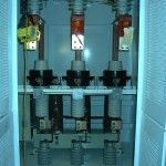
Air Core vs. Iron Core Reactors
Introduction
At the medium voltage level, 2.4kV through 34.5kV, harmonic filters are often designed, specified, and manufactured with either Iron-core or Air-core reactors. The preference for one reactor over the other may be from experience, familiarity, misconception, or some good technical reason. This document should help in presenting the major differences and benefits that exist between these two types of reactors.
Background
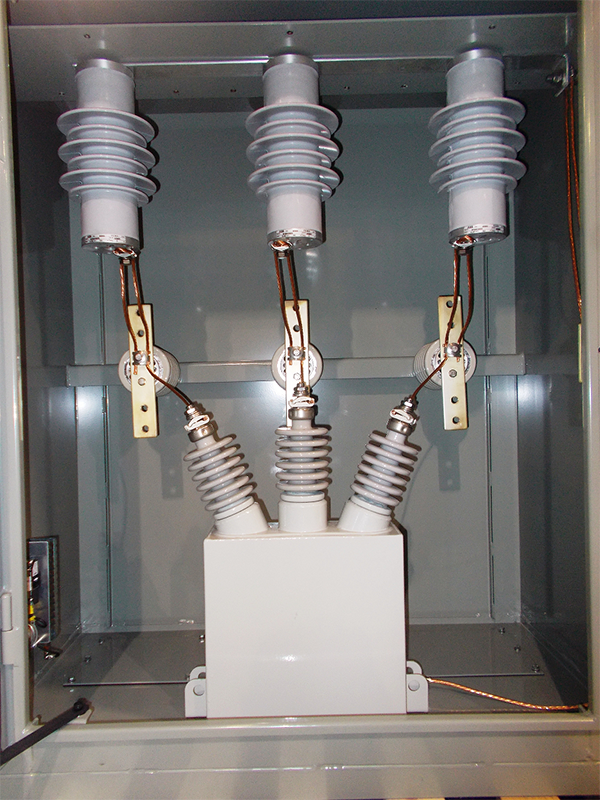
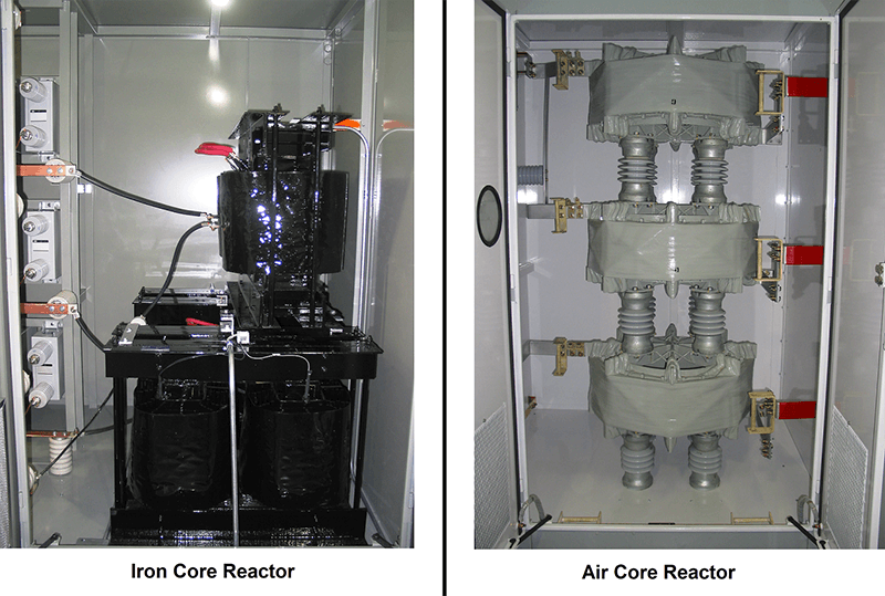
Figure one shows the physical characteristics of typical Iron-Core and Air-Core reactors utilized in harmonic filters. Iron core reactors usually consists of a copper winding wound around an iron core that has an air gap. The number of winding turns, area of the air gap, and length of the gap, determine the reactors inductance. Due to the high permeability of iron, the magnetic field is confined to the core, and the inductance of the reactor is accomplished with a low number of turns. The iron-core may be put at either line or ground potential. At line potential, the core would be supported on post insulators and the voltage gradient between the core and the winding would be minimal. When the iron-core is at ground potential, the winding-to-core insulation must be rated for the line potential.
The air-core reactor consists of either an aluminum or copper winding wound around and supported by an aluminum structure. The aluminum structure is typically floated at line potential with post insulators to minimize insulation requirements and cost. The air-core reactors inductance is primarily determined by the number of turns, height, and diameter of the reactor. It is usually large and consists of many turns as compared to and iron-core reactor with equal inductance. Since there is no iron, the stray magnetic field is quite high and it should be accounted for in the early stages of a harmonic filter design.
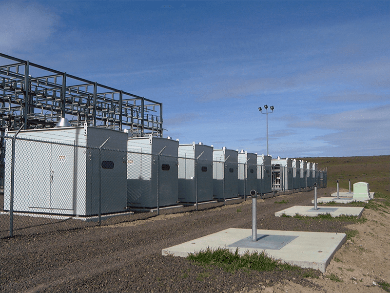
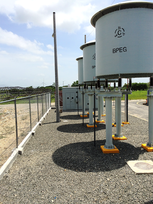
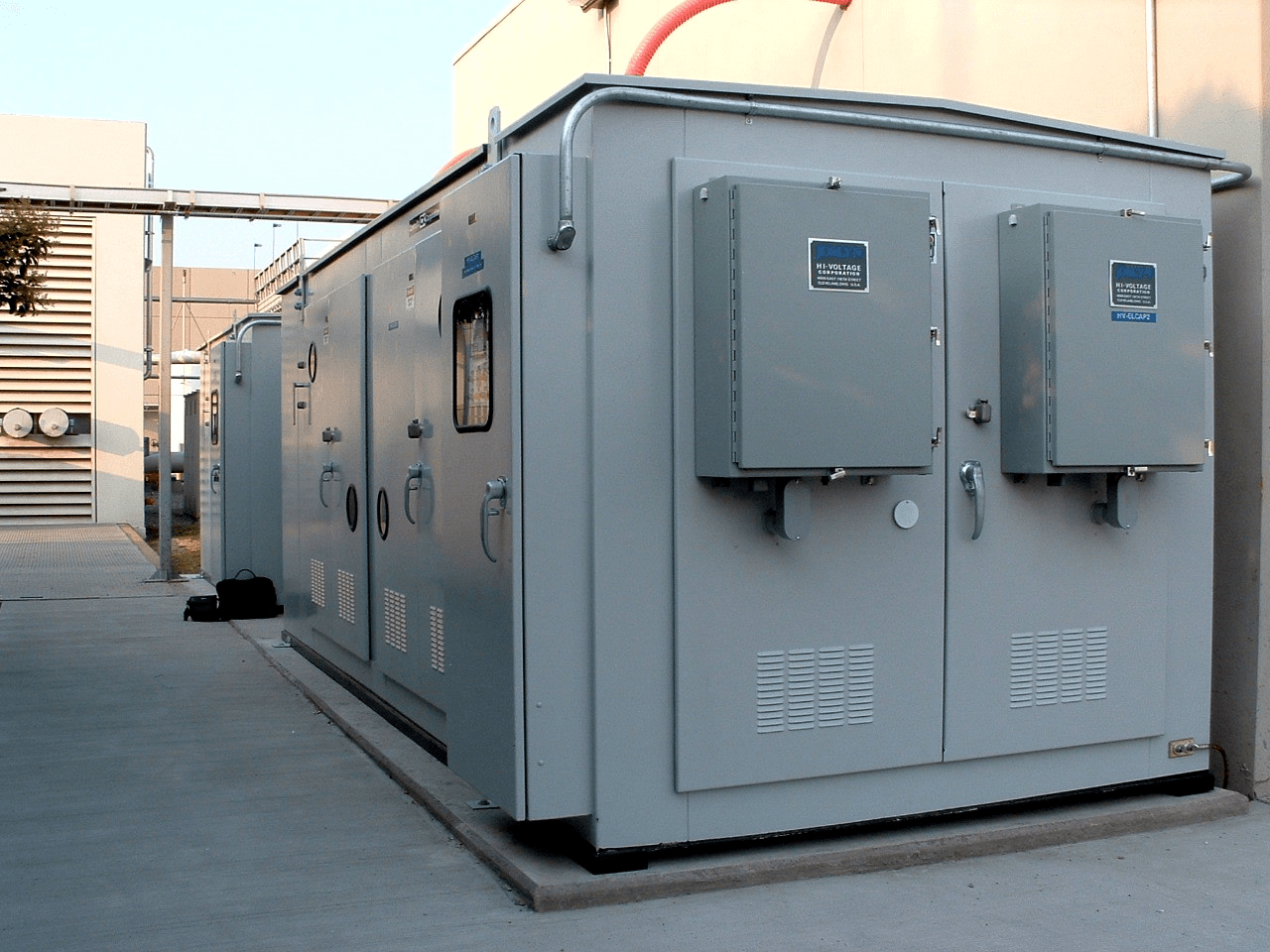
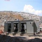
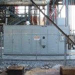
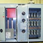
The type of reactor used typically determines the harmonic filter layout. Figure 2 shows how the type of reactor changes the physical characteristic and design of the filter. Air core reactors are typically associated with rack mounted capacitor banks and are mainly placed in substations. Iron-core reactors are usually placed inside enclosures which may be rated for indoor or outdoor locations.
Filter Performance
Issues
The question often arises over which reactor is superior for harmonic filter applications. Table 1 should help to answer this question. The table shows that there are both benefits and draw backs to both types of reactors. The major issues in regards to harmonic filters is primarily limited to stray magnetic fields, saturation, harmonic current rating and space requirements.
Stray Magnetic Fields
Air-core reactors have high stray magnetic fields. These fields may interfere with other power system equipment, produce eddy currents (which may cause heating) in nearby steel structures, and present a health hazard to people with pace makers and other medical devices. These problems may be reduced or eliminated by providing enough clearance around the reactor. Where real-estate is an issue, 3/8″ aluminum plates may be placed around the reactors (floor, ceiling, and even sides) to reduce external fields. Eddy currents can also be reduced by providing isolation (effectively breaking the current paths). In any case, the solution to stray magnetic fields may increase the cost of the installation. The reactor manufacturer should be consulted, and informed of nearby conducting bodies, since they may have an effect on the reactors inductance.
Saturation
Saturation is problem inherent in Iron-core reactors. The amount of flux, or flux density, that an iron-core reactor can carry is limited, and is dependent upon its cross-sectional area. The higher the cross-sectional area, the higher the amount of flux it can carry. The flux density is directly related to the peak current that the reactor will carry, which can be as high as the fundamental peak current plus the sum of the individual peak harmonic currents. This is seldom the case, but would lead to a very conservative reactor design. Less conservative designs assume a coincidence factor, which defines the peak current as a percentage of the sum of the harmonic peak current plus the fundamental peak current. The point to be made here, is the concern of saturation in iron-core reactors can be eliminated by proper design of the reactor. In specifying Iron-core reactors, the following points should be noted:
• The Iron-core reactor should be designed so that it will not saturate when the harmonic flux and fundamental flux is totally additive (coincidence factor of 1.0).
• Saturation should be defined as the point in which there is a 10% loss of inductance.
• The harmonic current spectrum should account for voltage regulation, manufacturing tolerances in both the reactors and the capacitors, and harmonic load growth.
If the above points are specified, saturation should not be of concern for Iron-core reactors.
Harmonic Current Rating (RMS)
The harmonic current rating is the vector sum of the harmonic currents, and is a concern in both Iron-core and Air-core reactors. The current rating determines the winding conductor cross sectional area and should be specified when ordering the reactor. The current should account for present and future harmonic load growth, plus increased fundamental and harmonic currents due to voltage regulation and manufacturing tolerances in the capacitors and the reactors. When specifying the reactor, the current spectrum should be specified since higher order harmonics have increased heating effects.
Space Requirements
Space requirements are usually a concern associated with Air core reactors due to the stray magnetic field. These fields can be reduced by shielding, but shielding can add cost to the bottom line. If shielding is necessary, it should be specified when ordering the reactor since it can have an effect on the reactor inductance. The following practices are usually followed when Air-core reactors are utilized:
• No metallic objects forming closed loops (re-bar, ground grid, ceiling joist, etc.) shall be within one diameter of the reactor. Typically, this would create a 12 foot x 12 foot area (assuming the reactors are stacked) with the reactor at the center. If the reactors are not stacked, more floor area would be necessary.
• Aluminum and sectionalized gasketed steel enclosures can have clearances down to 1/2 diameter between enclosure walls and the reactor.
• If re-bar directly below the reactor is of concern (or other metal forming loops), pedestals may be used to raise the reactors away from the floor, ceiling or ground. If the reactors can not be raised due to height limitations, a 12 foot x 12 foot x 3/8″ thick aluminum plate can be placed directly under the reactor for shielding.
• If health effects are of concern, the reactor manufacture should be consulted to determine the distance requirements to meet safe magnetic field levels. As a general rule, the magnetic field 1/2 diameter from the reactor will be approximately 30 Gauss. A thin wall enclosure will supply no shielding effect. To get lower fields, more space can be provided, or a 3/8″ Aluminum curtain (shield) around the reactor could be used. If personnel can come in contact with the aluminum curtain, a double wall enclosure may be be required due to excessive temperature of the Aluminum and the danger of burns.
Conclusion
Both Iron-core and Air-core reactors have benefits and disadvantages, but when properly designed, specified and applied, their performance is equivalent.
1Information provided compliments of Transformer Engineering Corporation, Cleveland, Ohio.